|
|
|
|
This paper was
presented at the SAE National Passenger-Car, Body and Materials Meeting,
Detroit, Michigan, March 7, 1956. John F. Adamson, Carl E. Burke and David B. Potter American Motors Corp.
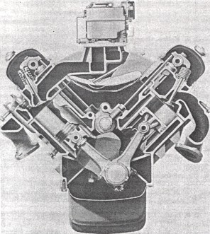
Enough has been said about V-8 engines, to preclude any discussion in this paper about the inherent advantages and disadvantages of this type of design. Rather, we shall attempt to set forth, not only the end results of our design and development efforts, but some of the more interesting problems involved in bringing the new American Motors V-8 engine to the automotive market. Many of the desirable design features pioneered by Nash and Hudson on our 6-cylinder power plants have been incorporated into this new V-8. We have drawn from a wealth of experience that includes 39 years of overhead-valve production at Nash, and the well-known ability of Hudson to develop high-performance engines. These features have been retained, in addition to ideas resulting from a very careful and thorough analysis of the newest industry-wide practices and methods. The above, together with a great deal of forward thinking, has produced an engine that will power a new series of cars; the Nash Statesman V-8, and the Hudson Hornet Special V-8 for 1956. Basic Design and Flexibility In addition to producing an engine with high performance characteristics, we had basically four other prime objectives in mind when we started to Put together the production version of our various experimental projects, engineering studies, and previously approved designs. We have through the years built a reputation for economical and dependable engines, and it was not our intention to sacrifice this or any other past objective in the new design. In short, we also wanted: 1. An engine that would be flexible enough to be readily adaptable to future displacement requirements, compression-ratio changes, and any of the other forward reaching, revisions of the automotive industry today. 2. An engine that could be easily installed in our present and future bodies, and would also lend itself to our methods of production assembly. At the same time, we wanted an installed engine that would be readily accessible for service. 3. An engine that incorporated the latest and most economical methods of manufacturing processes. 4. An engine with the lowest possible weight, without sacrificing durability. The new 3-1/2 in. bore by 3-1/4 in. stroke, 250-cu in. V-8 (Figs. 1 and 2) was designed to accommodate greater displacement than is actually being produced this year. As examples, the valve sizes were determined by future breathing requirements, as were both the intake and exhaust port systems. The crankshaft forging was designed to give 100% balance for much heavier reciprocating and rotating weights than now carried and the water and oil pumps have a greater capacity than presently required. The cylinder center distance of 4-3/4 in. is considerably larger than that required for a 3-1/2 in. bore, and allows for future increases without sacrificing coolant flow around the cylinder walls. Main bearing caps, bolts and connecting rods have likewise been designed for a greater load-carrying capacity.
Fig. 1- Transverse cross-section of American Motors V-8 engine
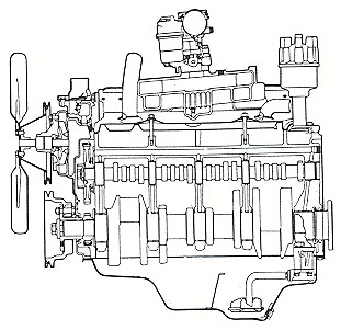
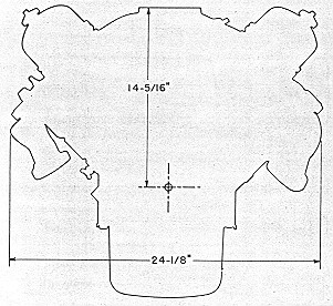
Fig. 2 - Longitudinal cross-section The above features, together with other factors will allow for increased engine displacement without extensive tooling changes. The crankshaft balancing equipment would be revised only with regard to "bob-weights," while no changes are needed on the block other than the pattern and machining revisions for bore size. As mentioned previously, the valves have been actually designed for a greater displacement, and consequently, the only chance required in the cylinder head for shifting to a bigger engine would be the revising of the cast combustion chamber. Engine Size With regard to engine size, we set out to produce an engine that could be easily installed in not only our present line of cars, but also those projected for the future. From the styling standpoint, it had to be a low engine, and from the assembly installation standpoint, it was desirable to minimize width and length. These objectives were obtained by making the term compact" the byword of the entire project. A short stroke of 3-1/4 in. was chosen to reduce height and width, and the crankshaft counterweights are contoured to further shorten the distance from the crankshaft centerline to the top of the block. Exhaust manifolds are carried below the port openings in the head, and the intake port facings are held parallel to the cross-sectional centerline of the banks to further reduce the height of the carburetor flange. As shown in Fig. 3, the above items allowed us to design an engine that has a width of 24-1/8 in. across the exhaust manifolds, and a height from the crankshaft centerline to the carburetor flange of 14-15/16 in. The overall length from the back face of the engine to the center of the fan pulley is 27-23/32 in. It must also be borne in mind that these dimensions will remain unchanged for an engine of greater displacement than the present 250 cu. in.
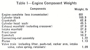
Fig. 3 - Engine outlline Although servicing an installed engine is one of the problems of V-8 design, a number of features were adopted to ease this problem. Spark plugs are located well above the exhaust manifolds, and are in a nearly vertical position for easier removal and installation. Service consideration was also given to the generator, as it is located at the upper right-hand side of the engine and outside of the tappet cover for easier accessibility. In addition, the distributor has a tang length, for mating with the oil pump shaft that allows this engagement to be made prior to engagement of the distributor gear with the camshaft drive gear. Manufacturing Exceptionally close liaison was maintained with our manufacturing personnel during the design and development stages of the engine. As a result, many economies in fabricating and tooling processes were built into the original design and have since been carried through into production. Tooling facilities for the V-8 are completely new, and are based on what we call "segmented automation." In this type of manufacturing, each basic section of tooling, although completely automatic, is not fully integrated with other sections. For our purposes, this type of tooling means increased flexibility as each portion of the line can be utilized independently of other operations. Of particular interest is the cylinder-block boring equipment, which has been designed to finish simultaneously blocks of two different bore dimensions. It contains two sets of roughing, finishing, and chamfering tools, and blocks of either bore size can enter the equipment in any mixed sequence. Each station is set to tool one size bore, and when a block enters that station, a probe automatically determines whether or not to cycle the cutting heads. Engine Weight The many features incorporated to keep engine height and length to an absolute minimum have aided tremendously in reducing engine weight. In addition, every possible design detail has been very carefully investigated for possible further weight reduction. Loading and stressing of all parts was painstakingly calculated to make sure that we were not guilty of over-designing. Regarding the loading and stressing of parts, all components, where applicable, were considered for use with the larger displacement versions of this engine. Consequently, even though the weight of the present production engines compares very favorably with competitive power-plants, the advantages of our weight-saving program will be much more apparent in future versions of this engine. Actual weights of the various major component parts are listed in Table 1.
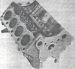
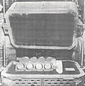
Table 1 - Engine component weights Cylinder Block As any engine is basically built in and around the cylinder block (Fig. 4), this component is the biggest factor in regard to power-plant size, weight, and flexibility. Even engine harshness and durability of the drive-train parts depend on the rigidity and design of the block. In the American Motors design, every effort has been made to provide a satisfactory base upon which to build the engine.
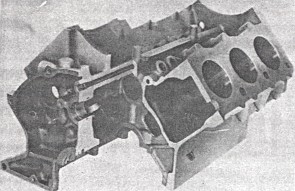
Fig. 4 - Cylinder block The crankcase flange has been carried 2-3/4 in. below the crankshaft centerline to provide inherent stiffness and a good oil pan sealing flange. The flywheel housing mounting surface provides a wide and deep base for drive-train mounting, and the 30 cylinder-head bolts give a pattern that carries the gas pressure load evenly into the water jacket walls rather than into the cylinder bores. This arrangement reduces distortion and consequent abnormal wear of the bores, pistons, and piston rings. (See Fig. 5.)
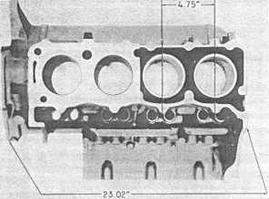
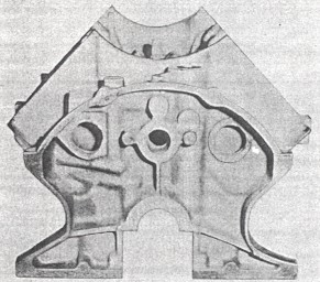
Fig. 5 - Cutaway of cylinder block showing design for rigidity Due to the fact that the block comprises the greatest weight of any component in the engine, it provides a lucrative field in which to effect weight reduction. We have taken advantage of this fact wherever our tests and previous experience has shown it to be possible. Working from the bore-to-bore distance of 4-3/4 in. established by future displacement needs, the overall length of the block has been held to 23.02 in. by careful consideration of coolant and loading needs, as shown in Fig. 6. Windows have been cast in the main bearing webs where strength requirements showed it possible, and as can be seen in Fig. 7, pockets have been cast on either side of the rear flange for further weight reduction. The right pocket nestles the starter close to the crankcase and allows the starter to be fastened to lightweight die-cast aluminum flywheel housing. It is obvious that we cancel several machining operations for a starter pad normally found on the block, and in addition omit a considerable amount of cast iron. We estimate that a saving of approximately 15 lb. of metal has been realized on the rear of the block alone.
Fig. 6 - Cyliner block dimensions
Fig. 7 - Cylinder block rear face You will notice in Fig. 8 that manufacturing savings have been obtained by eliminating hard sand cores wherever possible. Green sand has been provided for the front, side, top, and tappet chamber sections, and hard sand cores for only the crankcase, bores, water jackets, and rear face. All cores are machine set to minimize breakage.
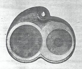
Fig. 8 - Cylinder-block core assembly Machining operations where also taken into account during the design stages of the engine, which resulted in the complete lack of any machining setup carried out for one drilling or surfacing operation only. Combustion Chamber We have chosen for this engine, a type of chamber that gives us what we consider the more important of the various characteristics obtainable for a good, efficient combustion chamber. The design used can best be described as a kidney-shaped, wedge-type, cast chamber. Excellent results have been obtained on our recent 6-cyl engines with this type of configuration, and it inherently contains a number of the factors we desired. Being cast, it requires a minimum of machining, and consequently, volume can be placed just where we want it. The kidney shape gives a swirling action to the intake gas for better turbulence, and spark-voltage requirements are quite low. As shown in Fig. 9, there is no shrouding of the valves and, therefore, a high volumetric efficiency is obtainable. Combustion characteristics are such that chamber shape controls the rate of pressure rise to minimize engine harshness. A compression ratio of 8.0:1 has been chosen to allow this engine to burn regular fuel and, therefore, further effect economy of operation.
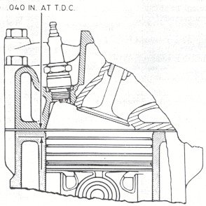
Fig. 9 - Cast combustion chamber As can be seen from Fig. 10, the spark plugs are effectively cooled by the considerable volume of water surrounding them. These plugs are located in the chamber in such a manner as to minimize the "drowning effects" of unvaporized fuel during cold starts. Fig. 11 shows the location of the plugs in the head.
Fig. 10 - Combustion chamber
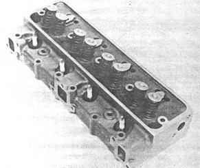
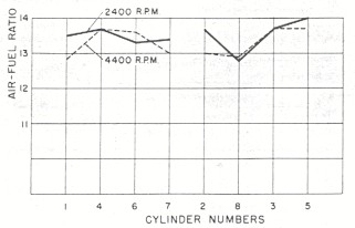
Fig. 11 - Cylinder head showing location of spark plugs Ports and Manifolds The purpose of induction and exhaust systems is efficiently to feed and scavenge an engine under all driving conditions. The intake manifold must be much more than just an inlet to a high-speed air pump, and the exhaust system must be scientifically balanced for the load it carries. Many major and minor chances were made in the intake manifold for this engine before the production version was agreed upon. Numerous cold and hot starting tests, plus runs under all operating conditions, were made in order to provide a manifold that would give the average driver a "satisfactory feeling" engine. Fig. 12 plots the air-fuel distribution by this manifold to the various cylinders under the conditions shown.
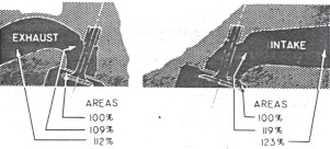
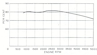
Fig. 12 - Fuel/air ratios Fig. 13 shows the basic configuration of the intake and exhaust port designs. Starting with the intake port opening in the head, it can be seen that a smoothly balanced transition is obtained in relation to the valve opening. The slight restriction of flow and consequent increase in gas velocity tends to develop a ram effect at the valve, with subsequent increase in engine torque. Valve size is such that the theoretical gas velocity through the valve is lower than that of any automotive engine on the market today. The full-throttle variation of volumetric efficiency with speed is shown in Fig. 14.
Fig. 13 - Intake and exhaust port areas
Fig. 14 - Volumetric efficiency at full throttle It can be seen that exhaust ports have also been designed to give balanced areas. Port size is increased as gases move away from the valve to give efficient scavenging and minimize backpressure. Exhaust manifolds are ample in area and provide for a smooth, continuous flow of exhaust gases. Coming in April, Part II of this SAE paper. |